Off the grid
Again, we are given a capture. This time it's the communication between a device an an OLED screen. We've also been given a schematic showing which channels go to which pins on the device.
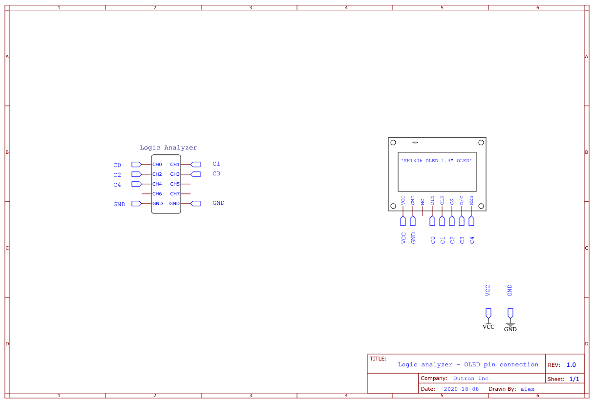
After a quick search we find that this OLED screen communicates over both i2c and SPI, with the pins in the schematic matching a 3-wire SPI interface.
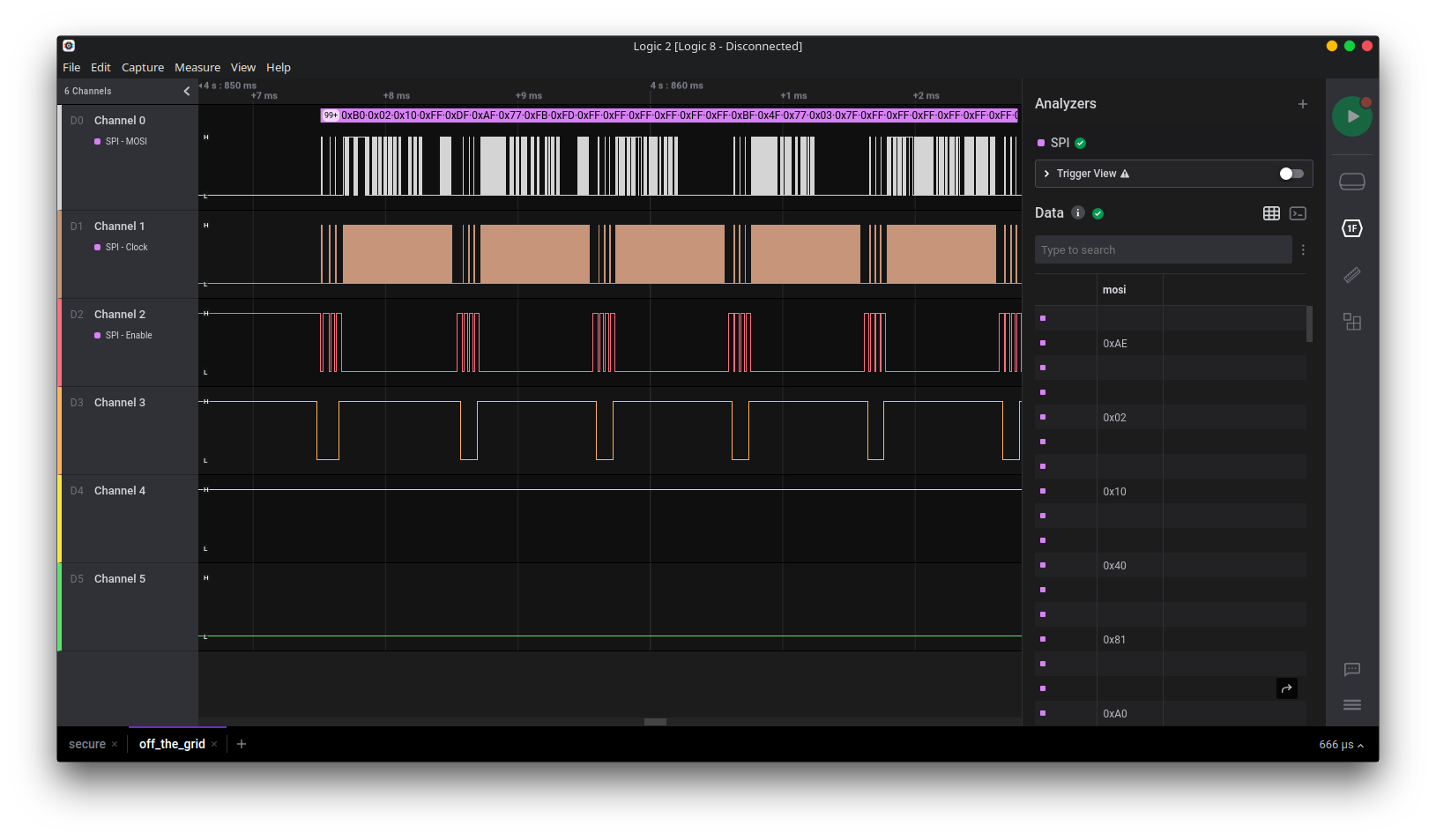
Loading an analyzer up in Saleae Logic we see this:
To figure out how this works I started reading the source of a rust implementation of a driver for this screen.
After some reading I find the sequences of bytes used to send different commands to the
display.
The command PageStart is used to signal an 8 pixel tall row is now going to be written to the given 'page'.
And the command ColStart is used to signal which column to start on.
Command::ColStart(addr) => ([0xF & addr, 0x10 | (0xF & (addr >> 4)), 0, 0, 0, 0, 0], 2),
Command::PageStart(page) => ([0xB0 | (page as u8), 0, 0, 0, 0, 0, 0], 1),
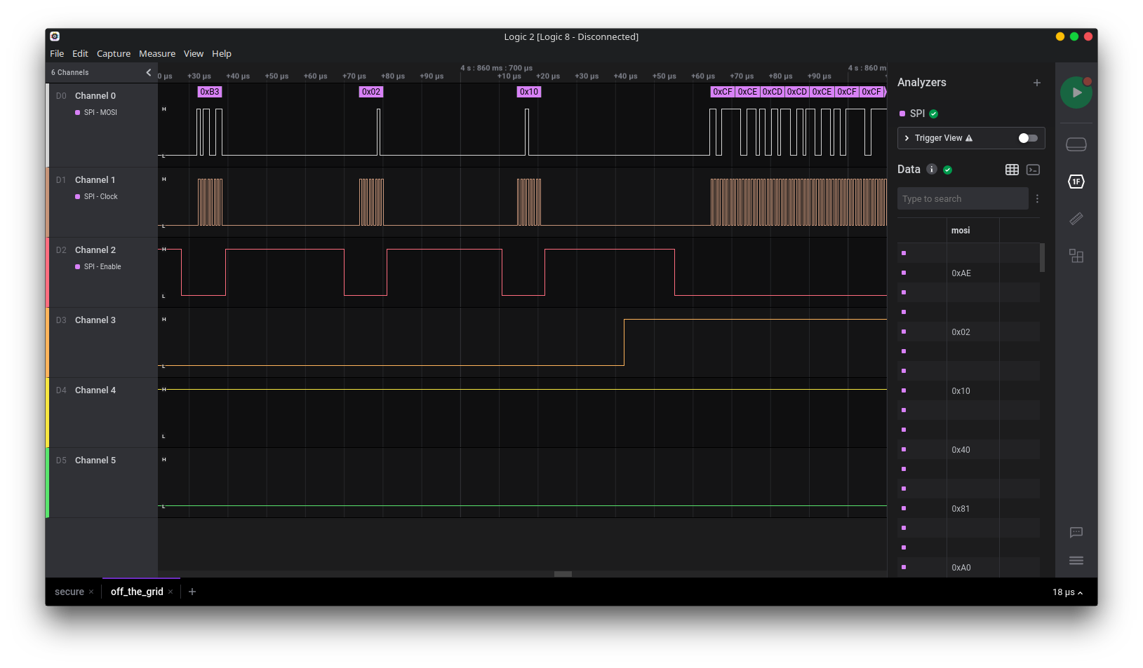
We can correlate this with the data transfer in the following screenshot,
we can see that first a 0xB3 is sent, signalling the third row is going to be written to,
and then some more commands. And then a long sequence of data is sent,
presumably this is the image data.
Looking at the code for emitting the image to the display, we see it just writes out the framebuffer over the SPI bus:
pub fn draw(&mut self, buffer: &[u8]) -> Result<(), DisplayError> {
    self.iface.send_data(U8(&buffer))
}
So we look at the code for setting the value of a single pixel, which boils down to:
/// Turn a pixel on or off. A non-zero `value` is treated as on, `0` as off. If the X and Y
/// coordinates are out of the bounds of the display, this method call is a noop.
pub fn set_pixel(&mut self, x: u32, y: u32, value: u8) {
    let idx = ((y as usize) / 8 * DSIZE::WIDTH as usize) + (x as usize);
    let bit = y % 8;

    if let Some(byte) = self.buffer.get_mut(idx) {
        // Keep track of max and min values
        self.min_x = self.min_x.min(x as u8);
        self.max_x = self.max_x.max(x as u8);
        self.min_y = self.min_y.min(y as u8);
        self.max_y = self.max_y.max(y as u8);

        *byte = *byte & !(1 << bit) | (value << bit)
    }
}
Seems the state of each pixel is stored such that each byte stores an 8 pixel high column of pixels, so I exported the data from Logic, and wrote a quick python script that takes the data for each of the 8 rows written to the display, and renders the resulting image.
from PIL import Image, ImageDraw

page0 = [

0xFF,
0xDF,
0xAF,
# ...
0x00,
0x00,
0x00,

]

im = Image.new("RGB", (128, 64))

def c(x,y):
    idx = (y // 8 * 128) + x
    bit = y % 8
    return idx, bit

for x in range(128):
    for y in range(8 * 8):
        idx, bit = c(x, y)
        byte = page0[idx]
        val = bool(byte & (1 << bit))
        col = 255 if val else 0

        im.putpixel((x, y), (col, col, col))

im.show()
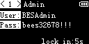
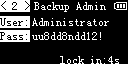
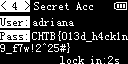
There were several frames shown on the screen, with one containing the flag:
 |
 |
 |
 |